Gibson Mercury
Service and Repair
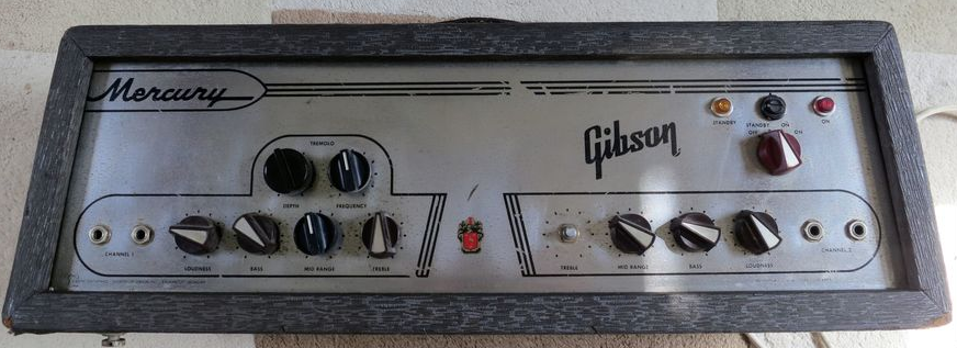
As a return favour I offered to have a look at a friend's Gibson Mercury head as it made noises when you taped it on top. Otherwise it appeared to be in pretty good working order. I knew this was likely a power tube gone rattly.
When I picked it up there were some other minor issues explained so I thought this would make a nice addition to the "blog", being a rare amp in the UK.
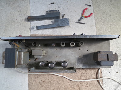
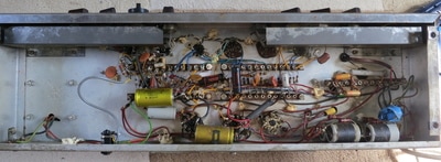
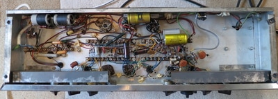
Back at the lab we took out the chassis and gave it a good eye-balling. Here's what we found (Why am I using the royal we?)
When I picked it up there were some other minor issues explained so I thought this would make a nice addition to the "blog", being a rare amp in the UK.
Back at the lab we took out the chassis and gave it a good eye-balling. Here's what we found (Why am I using the royal we?)
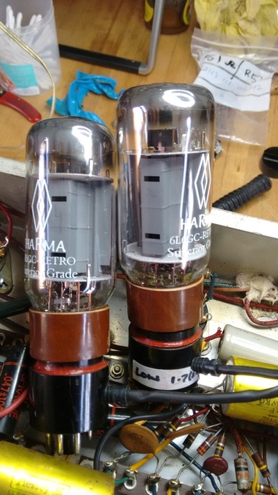
Firstly there was no schematic I could find with an EZ 34 rectifier and EL34 power tubes. The one that was closest was of no use whatsoever. All used 6L6GC valves for the output in fixed bias. This one was cathode biased with a 150 Ohm shared resistor. It had the wrong tubes fitted!
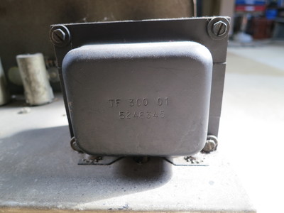
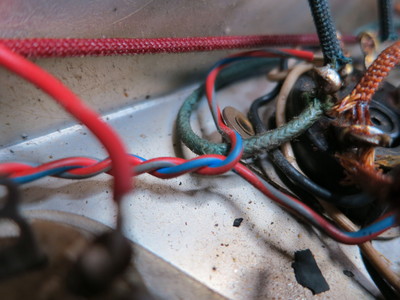
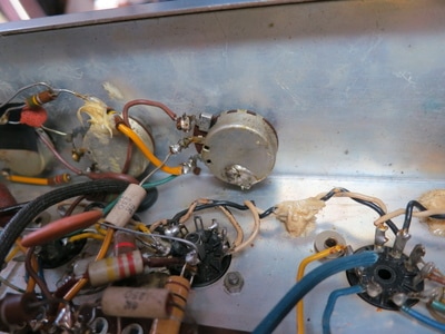
The amp appeared to be mostly original except it had been converted for 240V use in the UK. There were new holes drill in the chassis to accommodate the new PT, and the faceplate clearly states 110 - 125Vac. The OT and choke are original. It had certainly been worked on by at least two people, and one of them did not own a soldering iron.
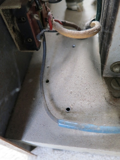
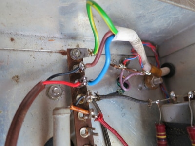
The worst point was the replacement mains cable had been crudely joined together (twisted wires) and covered in blue insulating tape. Hmmm! It just goes to show that when you buy an old amp you should at least have a tech look it over for potential dangers.
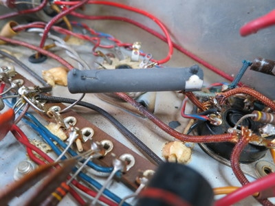
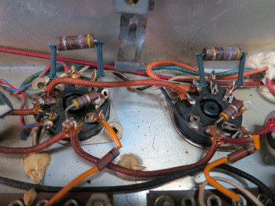
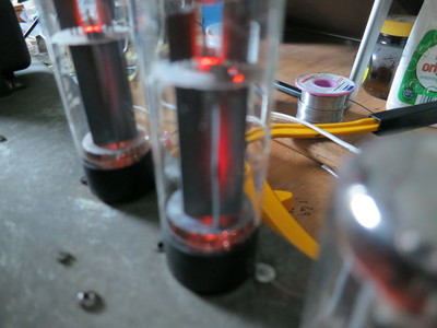
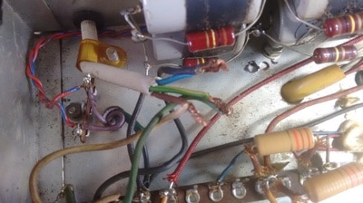
Looking closer revealed obvious signs of overheating power valves. Three resistors had cooked and needed replacing.
As the amp worked ok, I fired it up with my home made bias probes in place. The EL34s were pulling way too much current; 78.4 and 75.3mA at around 410Vdc plate to cathode. That's approximately 150% of safe plate dissipation. Had someone really put a great pair of Great British made Mullard xf2s in there and not bothered to check the bias!! The 150 Ohm shared cathode resistor looked like it had always been there. If you change the mains transformer, the bias is most likely going to need adjusting and the only way is to change the cathode resistor… or is it? Why is there an additional 47 Ohm resistor on each plate. I have seen this on Vox AC 30s and some old HI-Fi schematics. Perhaps they were to tame any parasitics.
Any way, here's a quick list of repairs carried out:
All electrolytic measured for capacitance and ESR (all surprisingly good!)
Resistors checked to spec.
3 broken rivets replaced (flappy power valve sockets)
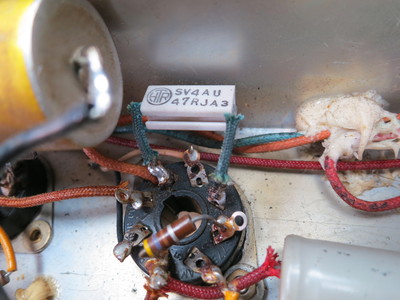
2 burned 47Ohm anode resistors replaced
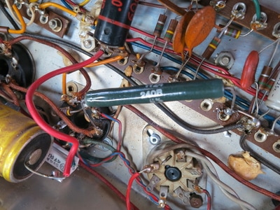
New pair of correct 6L6 GC installed and biased correctly with a NOS Welwyn high wattage 240 Ohm cathode resistor.
Mains cable adjusted and soldered in place.
General service and cleaning (dust / webs).
Input jacks re-tensioned so that they earth out when not in use (buzzy)
That's about it other than periodically checking bias and about 4 hours soaking to make sure everything is stable.
The Tremolo
The 10k depth pot crackled and I tried to replace it with a 220K as per the schematic. It didn't work so I ended up cleaning and putting the old one back, as time was an issue and I couldn't get hold of another 10K. The tremolo doesn't get used much but it acts as a gain boost when disengaged with a foot switch. If it does become a problem it's a 20 minute job to replace it.
It did appear that the tremolo circuit had been modified at some point and uses an ECC83. The schematic shows a 6C4 in that position, so another mystery and I'm glad I didn't have to try to fix it!

