Harmony H307X Overhaul
An Extremely Rare Model
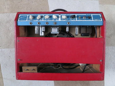
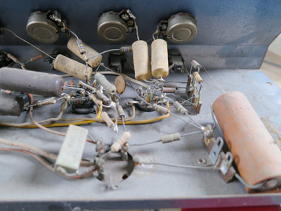
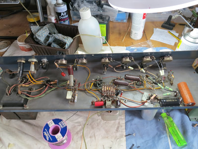
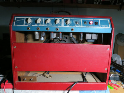
Now heres a rarity! It was brought to me having sat unused in an attic for about 20 years. It had no power tubes and was incredibly dusty inside. It needed a complete assessment of all its components before any electricity was applied. The owner stated that he thought the speaker was bad and would need replacing.
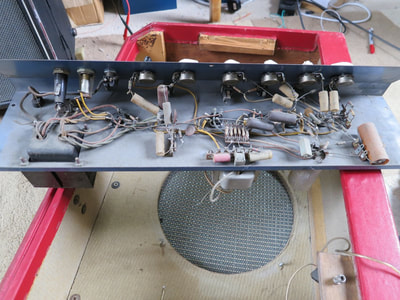
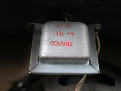
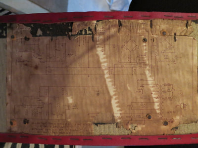
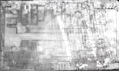
To start with, it needed a thorough dusting out and wipe-down of components to determine their values. The transformers checked ok with appropriate resistances, so all good there. There was a partial schematic attached to the inside of the back panel of the amplifier. I spent much time researching and repairing a digital copy of this in Fireworks! However, there was lots of damage and much of the circuit couldn't be deciphered. I couldn't find a schematic online but after literally hours of research, the closest circuit I founds was the S500 by Lectrolabs, who made some amps for Harmony. The S500 didn't have vibrato' but essentially the amp is the same.
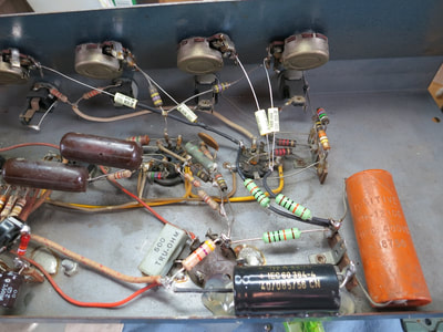
A visual inspection revealed that a 150 k resistor had detached from the Speed pot. I checked all the components that could be measured without desoldering, especially
the electrolytics for capacitance and ESR.
The first thing to check with an amp of unknown condition is that it's safe. The mains chassis ground and condition of mains cable was examined, then I refitted the mains plug, as the bare wire ends were corroded and replace the 13 Amp fuse with a 3 Amp one.
Initial power up with no valves and 40 Watt light bulb current limiter showed no shorts. This is a fixed bias amp requiring around -15VDC on the grids of the power tubes. This was measured and showed it was present but inadequate at just -12VDC. This fault would have caused the early demise of a pair of 6BQ5 valves. Experiments with different resistor values obtained a conservative voltage (-16VDC). To make things future proof and easier to bias I fitted a 10K adjustment pot allowing range of -17 to -14VDC.
All the valves were tested on my delicate but trusty Taylor 45C valve tester. The rectifier was good, one 12AX7 OK, the 6AU6 ok but slightly under emissions (Vibrato), but
one 12AX7 had poor emissions on one triode. It was replaced with new JJECC83s.
Power up with rectifier valve only with current limiter and load resistance for HT voltage checks.
Timed short periods only to allow old capacitors to reform.
The Speaker
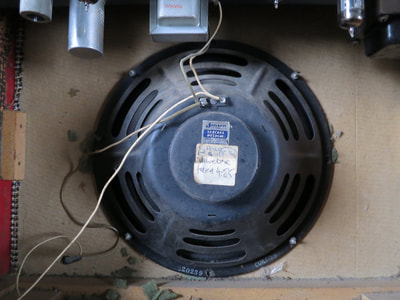
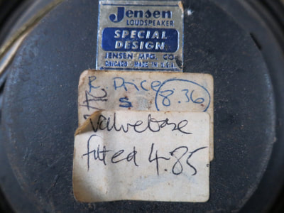
This was removed and the cone cleaned of dust. Continuity test revealed the coil was not open circuit and was an 8 Ohm speaker. The dust cap was half off so I vacuumed out any dust and checked for cone rub - none detected. The cabinet was vacuumed out to remove dust and old foam which had been inserter between speaker basket and baffle board. The four screws were a little loose. Finally the speaker and amp were reunited with the cabinet, all baffle screws tightened and the speaker nuts just hand tight.
Power up tests with all valves and current limiter
There was some output, but low and distorted. After 5 minutes there was an acute deterioration of sound quality indicating bad components. The vibrato was not working at all.
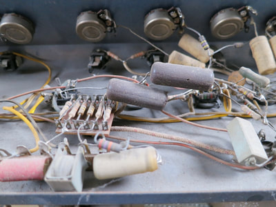
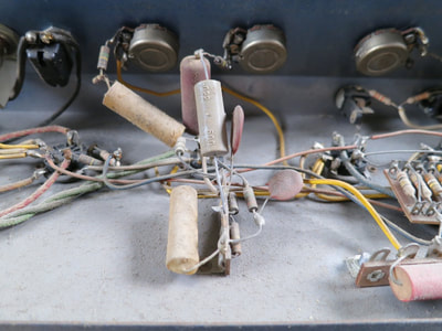
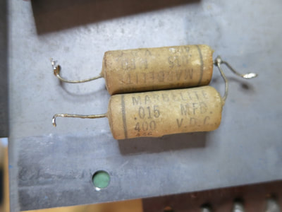
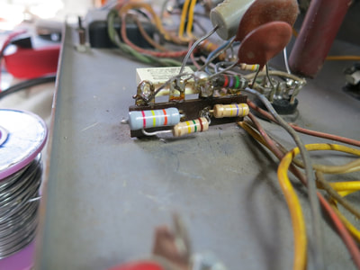
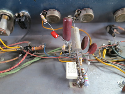
I soon discovered that all the old paper tone capacitors were leaking dc, so all four replaced with 0.01uF 400V Illinois caps. This made a huge difference but still some distortion present after warm up.
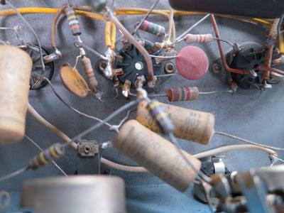
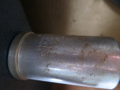
I then found several resistors had drifted out so far as to need replacing. It was noted that the main smoothing can capacitor was getting warm indicating leakage, though there was no hum audible. There was a lot of background hiss and spluttering indicating noisy 100k plate resistors on V1. These were replaced with 2 Watt metal film making a huge difference to the noise floor.
Voltages around V1 were also low, so I removed all components from the main 3 section can capacitor and measured for capacitance and ESR. The first section was bad with 9.8 Ohms ESR, no wonder it was getting warm! I decided to disconnect it from the circuit and put in a new F&T 22uF 500V capacitor under the chassis to preserve the vintage look. The other 2 sections measure excellent so were kept in circuit. I replaced the 100k and 47k dropper resistors connected to the can capacitor and this also helped with noise. A sound test revealed great tone and very low noise floor. The speaker is good! A cracker!
The Vibrato Circuit
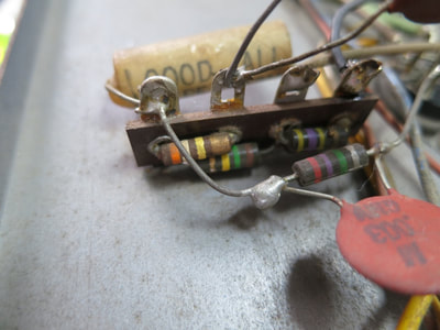
All the resistors had to be disconnected to get a reading. All were out and one was open circuit. I also replaced 2 more paper capacitors with modern equivalents.
Now it works great and is absolutely one of the best sounding vibratos I've heard! It's a rare one which modulates the negative bias to the power tubes, just like the Selmer Constellation 20.
Lastly I replaced 2 screws on the back board with longer ones and touched up the heads with some stained lacquer to blend them in.

